Inductor Coil Calculator Software Free Download

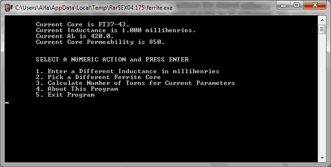
Coil Maestro Solenoid Inductance Calculator Software Download OVERVIEW: Program calculates optimal dimensions of coils for wanted inductance. It is simple to. Inductor Design Software You can easily design inductors using this application. We can enter micro Henry, Ohms, Amperes, Core shape, Winding type, Frequency.

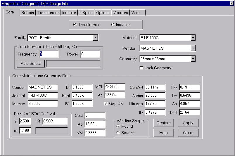
Magnetic Builder (Magnetic Design Software, Inductor and Transformer design tool) is a free web-based software providing power supply (SMPS) design, transformer design, magnetic design, loss analysis, thermal analysis, waveform analysis, MTBF analysis, BOM building, DVT analysis and optimization of power supply (SMPS). Magnetic Builder is a useful magnetic design software. It is a tool for user to create his/her own magnetic component (inductor and transformer) by selecting different ferrite core, bobbin type and winding method. Engineering drawing will be automatically produced to reduce user work load. All the transformer and inductor built can be saved and reused onto a power supply, as long as the winding number are matched.
Inductor/Transfomer are necessary parts of switching power supply circuits. The Advantages of Using Transformers Transformers used with the three basic topologies offer certain advantages over the simple circuits introduced in the previous section. Namely: • They provide isolation between input supply and output DC lines, and between one DC output line and another.
• Suitable choice of turns ratio can ensure that near optimum duty cycle is used, even when input and output voltages are widely different. • The buck, boost and flyback topologies provide outputs which are, respectively, lower, higher, or polarity reversed versions of the input supply. A transformer/inductor can effectively remove all these inherent constraints, and, by so doing, enable any special topological property to be taken advantage of, if desired. • A single regulator system can produce more than one separate DC output line by using a number of secondary windings. Reference Tutorial Index: • • • • • • • • • • • • • • • • • • • • • • • • • • • • • • • • • • • • • • • • • • • • • • • • • • • • • • Click “Magnetic Builder” a “Number of Windings” page appear for user to first defining the number of primary winding and number of secondary winding. The number of primary winding and number of secondary winding can be change. The default value is one.
• Move cursor to the winding • The winding will turn RED • Click on the winding and you can see the picture as below • Winding with the same number of turn will be shown and can be selected for bilfilar. Click the button “Flux Band” Two type of flux band are supported. Click the checkbox to add the flux band. After clicked the checkbox, the core with the flux band can be preview. The Flux band thickness and width can be set. Extra Winding can be added by clicking “Add Pri Wdg” or “Add Sec Wdg.” The usage of this feature is recommended for non-operating winding only. User is recommended to preset the proper winding number at the “Number of Windings” page.
The user can change a particular winding to Faraday Shield. Only extra windings can be changed to Faraday Shield. After creating a new transformer/inductor, you can add it to the design by pressing “Add Component”. When the transformer/inductor is added, the message with transformer's designator is shown.
Or parallel winding User can “Split” a winding to several section by choosing from “No. Of windings” or Parallel Winding in any winding for sandwiching winding method. Creative Sb Extigy Driver Windows 7 there. The winding order can be changed by the list box. W1 means the most inner layer.
For each winding The number of turns for each winding is shown in the blue button. You can press this button to modify the number of turns. The wire information for each winding is shown in the blue button. It shows the Wire name and the number of parallel wires. You can press this button to modify it. The “Total Loss” means the overall losses of the power supply and is shown at the top of the interface and will be automatically updated for any changed in transformer design. The “Transformer Loss” means the losses of the whole transformer and is shown at the top of the interface and will be automatically updated for any changed in transformer design.